Lab 3 - Blynk Application
How to setup Blynk app (mobile phone)
Installing and Getting Ready
1. Search for 'Blynk' and install the application.

2. You will have to create an account to proceed further. You can also log in with your Facebook account if you possess that.

Creating Project
3. After you have successfully signed in the following window will appear. Click 'New Project'.

4. Now specify the name of your project, device and connection type. After the press the 'Create' button.

5. You will receive a notification regarding your Authorization token. This can be accessed from the email account you signed in with and also through Project Settings.

6. Now the Blynk canvas will open as shown below:

7. Press on the screen. The widget box will appear. Now we will build our project. Firstly, we will press the 'Button' widget. You can view information regarding it by pressing the icon present in the far right as highlighted below.

8. Press the button widget again on the canvas to change its parameters. In the output section, choose the GPIO pin through which your LED will be connected to the ESP32 module. We have used GPIO25. You can use any other suitable output GPIO pin. Also, change the moded of the button to a 'SWITCH'.

9. After you alter the settings of the button the canvas will look something like this.

Icons
At the top, you will find three icons. These are for Project settings, editing and play button. Inside the play button, you can also find the stop button.

As we are building a fairly simple project thus, we do not need any other widgets besides the button. Our Blynk project is ready. Let us proceed with the Arduino IDE setting.
Installing Blynk library
1. To use the Blynk app with our ESP32 board, we would have to install its library.
2. To download the library, click here. Click on 'Code' and then 'Download Zip'

3. You have to go to Sketch > Include Library > Add .zip Library inside the IDE to add the library as well. After installation of the library, restart your IDE.
Arduino Sketch (Connecting ESP32 with Blynk)
Open your Arduino IDE and go to File > New to open a new file. Copy the code given below in that file. You need to enter your network credentials. Additionally, you also have to provide your Authorization key which you obtained from the Blynk app.
 #define BLYNK_PRINT Serial
 #include <WiFi.h>
 #include <WiFiClient.h>
 #include <BlynkSimpleEsp32.h>

 int led_gpio = 2;

 #define Authorization_key "hXBwHPyX-kvDSQAxkEq_R_A21x******"
 #define SSID "Write_your_SSID_here"    // replace with your SSID
 #define Password "********"      //replace with your password

 void setup() {
  pinMode(led_gpio, OUTPUT);
  Serial.begin(115200);
  delay(10);
  WiFi.begin(SSID, Password);
  while (WiFi.status() != WL_CONNECTED) {
  delay(500);
  Serial.print(".");
  }
  Blynk.begin(Authorization_key,SSID,Password);
 }
 void loop(){
   Blynk.run();
 }
Demonstration
1. Choose the correct board and COM port before before uploading your code to the board. Go to Tools > Board and select ESP32 Dev Module.

2. Next, go to Tools > Port and select the appropriate port through which your board is connected.

3. Click on the upload button to upload the code to your ESP32 development board. After you have uploaded your code to the development board, press its ENABLE button.

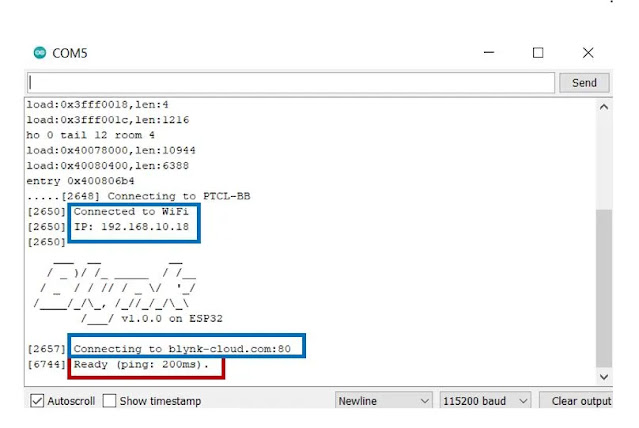
4. In your Arduino IDE, open up the serial monitor and yhou will be able to see the status of your WIFI connection. You will reveive different messages as shown below.
5. When you receive the 'ready' message on the serial monitor, open your Blynk application. Open the project you created and press the 'play' button.

6. Click the microcontroller icon at the top. You will receive a nofitication about the connection being established with your ESP32 board.

7. Now, touch the Button widget to toggle the LED. By pressing ON/OFF, simultaneously the LED connected to GPIO25 will turn ON/OFF as well. To disrupt the connection, press the stop button.

Example of simple application

Code
 #define BLYNK_TEMPLATE_ID "MP***a"
 #define BLYNK_DEVICE_NAME "La**"
 #define BLYNK_AUTH_TOKEN "lW9*******KNauG***"

 // Comment this out to disable prints and save space
 #define BLYNK_PRINT Serial

 #include <WiFi.h>
 #include <WiFiClient.h>
 #include <BlynkSimpleEsp32.h>

 //Output Pin
 #define LED_R 16
 #define LED_Y 17
 #define LED_G 5

 //Input Pin
 #define PB_Pin 4
 #define VR_Pin 35
 #define LDR_Pin 34
 #define MCP_Pin 39
 #define LM35_Pin 39

 #define VIN 3.3 // V power voltage, 3.3v in case of NodeMCU
 #define R 10000 // Voltage devider resistor value

 // Your WiFi credentials.
 // Set password to "" for open networks.
 char ssid[] = "Arond";
 char pass[] = "Ar1313";
 char auth[] = "lW9*******KNauG***";

 WidgetLED led1(V8);
 BlynkTimer timer;

 float get_VR(void)
 { float VR_Vout = (analogRead(VR_Pin)* VIN / float(4095));// Conversion analog to voltage
  float VR = ((R * VR_Vout) / VIN); // Conversion voltage to resistance in Ohm
  float VR_K = VR / 1000;
  return VR_K;
 }

 int get_lux(void)
 { float LDR_Vout = (analogRead(LDR_Pin)* VIN / float(4095));// Conversion analog to voltage
  float RLDR = (R * LDR_Vout)/(VIN - LDR_Vout); // Conversion voltage to resistance in Ohm
  int lux = 170/(RLDR/1000); // Conversion resitance to lumen, RLDR/1000 - convert Ohm to KOhm
  return lux;
 }

 float get_MCP9700(void)
 { float Temp_Vout = (analogRead(MCP_Pin) * VIN / float(4095)-0.5);// Conversion analog to voltage
  float temp = Temp_Vout / 0.01; // Conversion resitance to lumen, RLDR/1000 - convert Ohm to KOhm
  return temp;
 }

 float get_LM35(void)
 { float Temp_Vout = (analogRead(LM35_Pin) * VIN / float(4095));// Conversion analog to voltage
  float temp = Temp_Vout / 0.01; // Conversion resitance to lumen, RLDR/1000 - convert Ohm to KOhm
  return temp;
 }

 // This function sends Arduino's up time every second to Virtual Pin (5).
 // In the app, Widget's reading frequency should be set to PUSH. This means
 // that you define how often to send data to Blynk App.
 void myTimerEvent()
 {
  int PB_state = !digitalRead(PB_Pin);
  float VR_vlaue = get_VR();
  int lux_value = get_lux();
  float MCP_value = get_MCP9700();
  //float LM35_value = get_LM35();

  if(PB_state){led1.on();} else{led1.off();}
  //Blynk.virtualWrite(V8, PB_state);
  Blynk.virtualWrite(V4, VR_vlaue);
  Blynk.virtualWrite(V5, lux_value);
  Blynk.virtualWrite(V6, MCP_value);
  //Blynk.virtualWrite(V7, LM35_value);

  Serial.println("PB state: "+String(PB_state));
  Serial.println(String(VR_vlaue)+" KOhm");
  Serial.println(String(lux_value)+" LUX");
  Serial.println(String(MCP_value)+" 'C");
  //Serial.println(String(LM35_value)+" 'C");

  Serial.println();
 }

 // This function will be called every time Slider Widget
 // in Blynk app writes values to the Virtual Pin 1
 BLYNK_WRITE(V0)
 {
  int pinValue = param.asInt(); // assigning incoming value from pin V1 to a variable
  digitalWrite(LED_R, pinValue);
  Serial.print("V0 LED_R value is: ");
  Serial.println(pinValue);
 }

 BLYNK_WRITE(V1)
 {
  int pinValue = param.asInt(); // assigning incoming value from pin V1 to a variable
  digitalWrite(LED_Y, pinValue);
  Serial.print("V1 LED_Y value is: ");
  Serial.println(pinValue);
 }

 BLYNK_WRITE(V2)
 {
  int pinValue = param.asInt(); // assigning incoming value from pin V1 to a variable
  digitalWrite(LED_G, pinValue);
  Serial.print("V2 LED_G value is: ");
  Serial.println(pinValue);
 }


 void setup()
 {
  // Debug console
  Serial.begin(115200);

  pinMode(LED_R, OUTPUT);
  pinMode(LED_Y, OUTPUT);
  pinMode(LED_G, OUTPUT);
  //pinMode(PB_Pin, INPUT_PULLUP);

  Blynk.begin(auth, ssid, pass);
  // Setup a function to be called every second
  timer.setInterval(1000L, myTimerEvent);
 }

 void loop()
 {
  Blynk.run();
  timer.run(); // Initiates BlynkTimer
 }
Blynk


Demonstration
Task of the day
1. Convert raw ADC value to LUX
2. Based on the LUX value:
- If high - only on the green is on
- If medium - only on the yellow is on
- Else - only on the red is on
 #define BLYNK_TEMPLATE_ID "T***Aa"
 #define BLYNK_DEVICE_NAME "Lab3"
 #define BLYNK_AUTH_TOKEN "IwUW****jfKNauGFqd"

 // Comment this out to disable prints and save space
 #define BLYNK_PRINT Serial

 #include <WiFi.h>
 #include <WiFiClient.h>
 #include <BlynkSimpleEsp32.h>

 //Output Pin
 #define LED_R 16
 #define LED_Y 17
 #define LED_G 5

 //Input Pin
 #define PB_Pin 4
 #define VR_Pin 35
 #define LDR_Pin 34
 #define MCP_Pin 39
 #define LM35_Pin 39

 #define VIN 3.3 // V power voltage, 3.3v in case of NodeMCU
 #define R 10000 // Voltage devider resistor value

 // Your WiFi credentials.
 // Set password to "" for open networks.
 char ssid[] = "***";
 char pass[] = "***";
 char auth[] = "I65****GFqd";

 WidgetLED led1(V8);
 BlynkTimer timer;

 float get_VR(void)
 { float VR_Vout = (analogRead(VR_Pin)* VIN / float(4095));// Conversion analog to voltage
  float VR = ((R * VR_Vout) / VIN); // Conversion voltage to resistance in Ohm
  float VR_K = VR / 1000;
  return VR_K;
 }

 int get_lux(void)
 { float LDR_Vout = (analogRead(LDR_Pin)* VIN / float(4095));// Conversion analog to voltage
  float RLDR = (R * LDR_Vout)/(VIN - LDR_Vout); // Conversion voltage to resistance in Ohm
  int lux = 170/(RLDR/1000); // Conversion resitance to lumen, RLDR/1000 - convert Ohm to KOhm
  return lux;
 }

 float get_MCP9700(void)
 { float Temp_Vout = (analogRead(MCP_Pin) * VIN / float(4095)-0.5);// Conversion analog to voltage
  float temp = Temp_Vout / 0.01; // Conversion resitance to lumen, RLDR/1000 - convert Ohm to KOhm
  return temp;
 }

 float get_LM35(void)
 { float Temp_Vout = (analogRead(LM35_Pin) * VIN / float(4095));// Conversion analog to voltage
  float temp = Temp_Vout / 0.01; // Conversion resitance to lumen, RLDR/1000 - convert Ohm to KOhm
  return temp;
 }

 // This function sends Arduino's up time every second to Virtual Pin (5).
 // In the app, Widget's reading frequency should be set to PUSH. This means
 // that you define how often to send data to Blynk App.
 void myTimerEvent()
 {
  int PB_state = !digitalRead(PB_Pin);
  float VR_vlaue = get_VR();
  int lux_value = get_lux();
  float MCP_value = get_MCP9700();
  //float LM35_value = get_LM35();

  if(PB_state){led1.on();} else{led1.off();}
  //Blynk.virtualWrite(V8, PB_state);
  Blynk.virtualWrite(V4, VR_vlaue);
  Blynk.virtualWrite(V5, lux_value);
  Blynk.virtualWrite(V6, MCP_value);
  //Blynk.virtualWrite(V7, LM35_value);

  Serial.println("PB state: "+String(PB_state));
  Serial.println(String(VR_vlaue)+" KOhm");
  Serial.println(String(lux_value)+" LUX");
  Serial.println(String(MCP_value)+" 'C");
  //Serial.println(String(LM35_value)+" 'C");

  Serial.println();
  if(lux_value>80){
   digitalWrite(LED_G,HIGH);
   digitalWrite(LED_Y,LOW);
   digitalWrite(LED_R,LOW);
  }
  else if(lux_value>=15 && lux_value<=80){
   digitalWrite(LED_Y,HIGH);
   digitalWrite(LED_G,LOW);
   digitalWrite(LED_R,LOW);
  }
  else if(lux_value<15){
   digitalWrite(LED_R,HIGH);
   digitalWrite(LED_G,LOW);
   digitalWrite(LED_Y,LOW);
  }

 }

 // This function will be called every time Slider Widget
 // in Blynk app writes values to the Virtual Pin 1
 BLYNK_WRITE(V0)
 {
  int pinValue = param.asInt(); // assigning incoming value from pin V1 to a variable
  digitalWrite(LED_R, pinValue);
  Serial.print("V0 LED_R value is: ");
  Serial.println(pinValue);
 }

 BLYNK_WRITE(V1)
 {
  int pinValue = param.asInt(); // assigning incoming value from pin V1 to a variable
  digitalWrite(LED_Y, pinValue);
  Serial.print("V1 LED_Y value is: ");
  Serial.println(pinValue);
 }

 BLYNK_WRITE(V2)
 {
  int pinValue = param.asInt(); // assigning incoming value from pin V1 to a variable
  digitalWrite(LED_G, pinValue);
  Serial.print("V2 LED_G value is: ");
  Serial.println(pinValue);
 }


 void setup()
 {
  // Debug console
  Serial.begin(115200);

  pinMode(LED_R, OUTPUT);
  pinMode(LED_Y, OUTPUT);
  pinMode(LED_G, OUTPUT);
  //pinMode(PB_Pin, INPUT_PULLUP);

  Blynk.begin(auth, ssid, pass);
  // Setup a function to be called every second
  timer.setInterval(1000L, myTimerEvent);
 }

 void loop()
 {
  Blynk.run();
  timer.run(); // Initiates BlynkTimer
 }
- When lux value is more than 80, GREEN led will ON.
- When lux value is more than 15 and less than 80, YELLOW led will ON.
- When lux value is less than 15, RED led will ON.